Positioning of Smoke & Heat Alarms
The positioning of your smoke and heat alarms is important in order to ensure effective detection in the event of a fire. Each smoke and heat alarm will have positioning instructions within the supplied user manual; however, please find below some helpful tips and a basic guide to the position of detectors within the home. Please note: it is your responsibility to make sure that the detector locations comply with any applicable building regulations.
Flat Ceiling
Smoke alarms should ideally be installed in the centre of the ceiling. It is recommended to position the alarm at least 300mm away from walls and light fittings/decorative objects (See fig 1.). This is because air does not circulate effectively in corners, and objects like light fittings can obstruct smoke and heat from entering the sensor chamber.
As hot smoke initially rises and then spreads out, smoke alarms should be located on the ceiling. This is so that smoke can reach the detector?s sensor chamber as early as possible. If it is not possible to install the smoke detector on the ceiling, the unit can be installed up to 575mm below it. A heat detector should also be located directly on the ceiling; however if this is not possible, the unit can be installed up to 125mm below it.
Sloped Ceiling
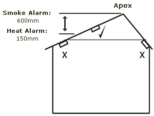
With a sloped ceiling the position of a smoke or heat detector needs to be measured vertically from the peak. Smoke alarms can be installed within 600mm and heat detectors can be installed within 150mm of the peak (See fig 2.). Again, it is important to try and position the detector as central to the ceiling as possible.
Fig 1. Positioning on flat ceilings
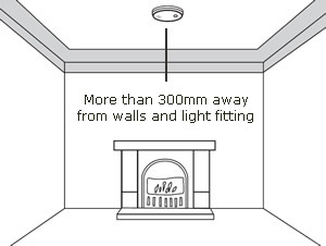
Fig 2. Positioning on sloped ceilings
Please note: The measurements stated above are a general guideline. Different manufacturers recommendations may vary.
Manual Fire Alarm Boxes
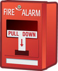
The most basic fire alarm initiating device is a manual pull station. These actually started being used on the streets back in the mid 1800s and are still used in a few locations today, primarily in New England. The technology of manual fire alarm boxes for fire alarm systems really hasn't changed since then. They are still mechanical switches that close a circuit and cause the control to go into alarm. With today's addressable systems, the control can identify the specific pull station that was activated, but the operation is the same “ a mechanical switch.
Most national fire and building codes today allow manual fire alarm boxes to be eliminated if the building is fully sprinklered. Why? Because of nuisance alarms caused by malicious activation of the manual station. There is an assortment of covers to deter nuisance alarms. One type has a battery-operated sounder that will activate if the cover is raised. This can reduce nuisance alarms, but some jurisdictions do not allow their use because there have been a number of cases where someone lifted the cover, heard the sounder, and assumed they activated the fire alarm system, so never pulled the pull station.
NFPA 72, the National Fire Alarm Code, has a requirement for at least one manual fire alarm to be installed for every system that has automatic devices such as smoke detectors or waterflow switches. This is meant to provide an additional level of safety for the occupants of the building. One of the primary purposes of this device is to allow occupants to have a means to manually activate the system if they see a fire rather than waiting for the smoke detector or waterflow switch to operate. The second purpose is to have a means for sprinkler repair personnel to activate the system in case of fire when the sprinkler system is down for service.
Manual stations must be installed between 42 inches and 54 inches to the operating part of the manual station and must be installed within 5 feet of the exit. A good rule of thumb is to always install manual stations at 48 inches to the top. This way, regardless of where the handle is, it will always comply with both NFPA 72 and the ADA.
If you look in the International Building Code or NFPA 101, Life Safety Code, you will see that “ other than manual fire alarm boxes and of course, sprinklers “ smoke detectors are the most common type of initiating device. You will find there are very few requirements for heat detectors.
Heat Detectors
Heat detectors are the least expensive of the automatic fire detectors available. This, of course, comes with a disadvantage. They are the slowest to react to a fire. Most heat detectors are used as a substitute for smoke detectors where the environment does not allow the use of a smoke detector. They are not considered life safety devices. Most fire deaths are caused by smoke inhalation, not from heat, so they are typically used in unoccupied locations as property protection devices. In fact, in the International Building Code, there is a statement that says if the space is sprinklered, you don't need to install heat detectors. After all, a sprinkler head is nothing more than a heat detector that allows water to flow.
The listed spacing for heat detectors varies depending on the type of detector and its rated temperature, although the most common listed spacing is 50 feet between detectors. The higher the rated temperature (the temperature that it will alarm) the closer the detectors must be installed to one another. The various types of heat detectors include fusible element, bi-metallic and rate compensation fixed temperature, rate-of-rise, and line-type.
Combination fusible element fixed temperature and rate-of-rise detectors are the most common. You may also find an application for a line-type heat detector, such as Protectowire. This type of heat detector is commonly used to protect cable trays, fuel lines, cooling towers, freezers and the like.
Smoke Detectors
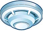
The most common type of automatic fire detector is a smoke detector. The building and life safety codes tell you where smoke detectors are required; NFPA 72 tells you how to install and test them. Some of the more common locations for smoke detectors are in corridors, elevator lobbies and machine rooms, and sleeping rooms.
It is vitally important to understand how smoke detectors operate for two reasons. One reason is to reduce nuisance alarms caused by environmental conditions or occupant activities. NFPA 72 has very good explanatory information in Annex A that describes these conditions. The second reason is to allow the detector to activate in the earliest amount of time. Smoke detectors are used where early warning is necessary to give occupants more time to safely exit a building.
There are basically three types of smoke detectors: ionization, photoelectric and air sampling.
An ionization detector uses a very small amount of a radioactive material to ionize air between two charged plates, causing a current flow. When smoke enters the ionization chamber, the smoke is attracted to the ionized particles and that will reduce the current flow. Once the current drops to a pre-determined level, the detector will alarm. Some sources of potential problems for ionization detectors are excessive air velocity or gusts of wind, most types of fumes and vapors, such as cooking fumes, engine exhaust and chemical fumes.
Photoelectric detectors come in two types: area or spot-type, and projected beam smoke detectors. Spot-type detectors are often referred to as light-scattering smoke detectors because there is a light source in the chamber (usually a pulsed infrared LED) that shines into the detection chamber. If there is smoke (or steam, dust or insects) in the chamber, the light will reflect onto a photosensitive sensor, causing an alarm. To reduce nuisance alarms, care must be taken to avoid using photoelectric smoke detectors in steamy or dirty environments.
Air sampling smoke detectors are very early warning detectors used in data processing centers or similar environments. These operate by having a piping network with sampling ports installed in the area to be protected. Air is drawn through this piping network back into the detection chamber where a laser typically is used to look for a certain number of smoke particles in a given amount of time. These detectors can be set up to be very sensitive and are often used as a first warning of a potential problem.

Smoke detectors do not have a listed spacing. They have a recommended spacing of 30 feet be-tween detectors. However, smoke detectors can be installed up to 41 feet apart in corridors up to 10 feet wide. The main fact to remember is that all points on the ceiling must be within 21 feet of the detector.
One of the more common installation problems with smoke detectors is installing them too close to air vents. NFPA 72 recommends that they should not be installed closer than 3 feet from any supply air diffuser or return vent. If they are too close to the supply, smoke may not reach the detector. Also, the air coming out of the vent contains dust and dirt, which can settle in the detector and cause nuisance alarms. Air turbulence can affect detector response when located too close to the return vents. Smoke detectors should never be installed within 4 inches of a ceiling or side wall. This is considered dead air space, and again may affect the activation time of the detector.
Today's technology has dramatically reduced the quantity of nuisance alarms caused by improper operation of smoke detectors. New smart smoke detectors are designed to reduce nuisance alarms by utilizing more than one technology. Some detectors incorporate both photoelectric and thermal technologies that interact to maximize detection. These new detectors have an onboard microprocessor that evaluates the conditions to reduce nuisance alarms. The photoelectric portion is best for smoldering fires and the thermal portion utilizes a rate-of-rise feature to provide faster response to flaming fires. Other new smoke detectors use a laser diode instead of the usual LED (light emitting diode). This allows for greater sensitivity while reducing nuisance alarms by verifying the nature of the scattered light in the chamber to determine whether the source is smoke or dust.
When testing smoke detectors, be sure you use an aerosol or canned smoke that is acceptable to the manufacturer. NFPA 72 requires that you test the detectors in place to ensure smoke entry into the chamber and an alarm response. Testing with a magnet does not meet this requirement. You must use this testing method for the acceptance test and the annual tests required by NFPA 72. You can use a magnet any other time, but not during those two times.
Projected beam smoke detectors are used in applications where it is not practical to use spot-type detectors. Common applications include use in high ceiling areas such as atriums. NFPA 72 states that all fire alarm devices must be accessible for servicing and testing. It is much easier and more cost effective to service a beam detector located on the wall of an atrium than it is to service the spot-type detectors located on the ceiling. Other common applications include use in barns, warehouses, stadiums and ballrooms.
One advantage of using beam detectors is that some are listed to operate at a temperature of about 20 degrees (F) below zero, unlike spot-type detectors which only are listed down to 32 degrees (F).
Another advantage is that the transmitter and receiver can be installed up to about 300 feet apart. On smooth ceilings each beam can be separated by up to 60 feet from the next beam. Two important installation considerations are ensuring the beam detectors, especially the transmitter, is installed on a secure wall, and secondly to make sure the beam is aligned properly. Projected beam detectors use a light obscuration method, which means that if some of the light is blocked from reaching the receiver, it will go into alarm. Misalignment of the beam gives the same results because there will be less light reaching the receiving unit.
Duct Smoke Detectors
Duct smoke detectors are used to help prevent smoke from spreading from the fire area to other parts of the building by shutting down the HVAC system. They also may be used to help protect the air handling equipment by shutting down the system if the fan or filter should start burning. When used with smoke control systems to re-direct the airflows in the building, they control smoke dampers in the ductwork, thus changing the direction of airflow, instead of shutting down the air handling systems.
One of the challenges with installing duct smoke detectors is that there are two codes that govern their use, NFPA 90A, Standard for the Installation of Heating, Ventilation and Air Conditioning Systems, and the International Mechanical Code (IMC). NFPA 90A requires a duct detector on the supply side of air handling systems that have an airflow greater than 2000 CFM (cubic feet per minute) and also on the return side if the unit is greater than 15000 CFM and it serves more than one floor. The IMC only requires a detector on the return side of units over 2000 CFM.
The challenge is to know which code is enforced in your area, or if both are enforced. If any of your Authorities Having Jurisdiction (AHJ) enforce NFPA 1, NFPA 101 or NFPA 5000, they all reference NFPA 90A. If your AHJs enforce the International Building Code, it references the IMC. In quite of number of jurisdictions, the fire department enforces NFPA 1 and/or 101 and the building department enforces the IBC. In that scenario, you would end up installing duct smoke detectors on both sides to make all of the AHJs happy.
Radiant Energy Fire Detectors
There are two types of radiant energy fire detectors: flame detectors and spark-ember detectors. Both are typically used to activate a suppression system in explosive environments. Radiant energy fire detectors are the fastest of all automatic fire detectors to respond to a fire because radiant energy travels at the speed of light. You will see them commonly used in places like aircraft hangers, fuel loading docks, clean rooms and anywhere else the risk of explosion exists. Spark-ember detectors are typically used to detect embers in areas where there are combustible dusts, like a grain conveyor system. Both types of systems activate suppression systems rapidly to avoid explosions or rapidly growing fires.
Regardless of the type of fire alarm initiating devices you install, remember that you will find the requirements for that device in your building, fire or life safety code and you will find the installation and testing requirements in NFPA 72. Be sure to have copies of both in your office. They are invaluable tools to help you properly install reliable fire alarm systems.
A Closer Look at the CodeManual stations must be installed between 42 inches and 54 inches to the operating part of the manual station and must be installed within 5 feet of the exit. A good rule of thumb is to always install manual stations at 48 inches to the top. This way, regardless of where the handle is, it will always comply with both NFPA 72 and the ADA.
The listed spacing for heat detectors varies depending on the type of detector and its rated temperature, although the most common listed spacing is 50 feet between detectors. The higher the rated temperature (the temperature that it will alarm) the closer the detectors must be installed to one another.
The building and life safety codes tell you where smoke detectors are required; NFPA 72 tells you how to install and test them.
Smoke detectors do not have a listed spacing. They have a recommended spacing of 30 feet between detectors. However, smoke detectors can be installed up to 41 feet apart in corridors up to 10 feet wide. The main fact to remember is that all points on the ceiling must be within 21 feet of the detector.
When testing smoke detectors, be sure you use an aerosol or canned smoke that is acceptable to the manufacturer. NFPA 72 requires that you test the detectors in place to ensure smoke entry into the chamber and an alarm response. Testing with a magnet does not meet this requirement. You must use this testing method for the acceptance test and the annual tests required by NFPA 72. You can use a magnet any other time, but not during those two times.
Projected beam smoke detectors are used in applications where it is not practical to use spot-type detectors. Common applications include use in high ceiling areas such as atriums. NFPA 72 states that all fire alarm devices must be accessible for servicing and testing.
Regardless of the type of fire alarm initiating devices you install, remember that you will find the requirements for that device in your building, fire or life safety code and you will find the installation and testing requirements in NFPA 72.
There are two codes that govern the use of duct smoke detectors: NFPA 90A, Standard for the Installation of Heating, Ventilation and Air Conditioning Systems, and the International Mechanical Code (IMC). NFPA 90A requires a duct detector on the supply side of air handling systems that have an airflow greater than 2000 CFM and also on the return side if the unit is greater than 15000 CFM and it serves more than one floor. The IMC only requires a detector on the return side of units over 2000 CFM.


